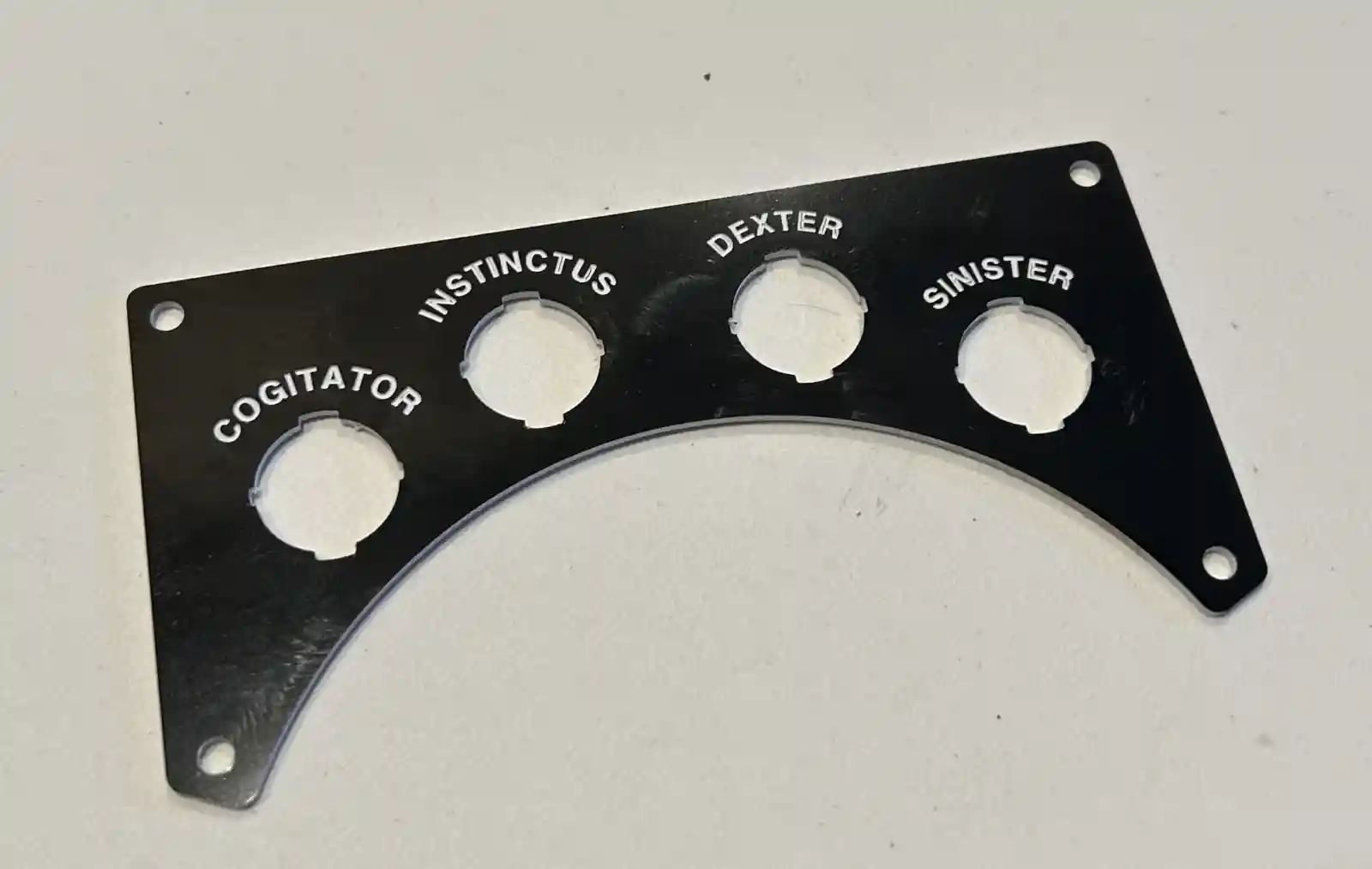
Jekyll2026-05-16T00:01:30+00:00https://robotics.ninthyard.com/feed.xmlDMC RoboticsCalvin is an open-hardware two-wheel self-balancing robot. This site is a working development log on the hardware, firmware, perception, planning, and control.Damon CaliEngraving Plastic2026-04-11T02:35:00+00:002026-04-11T02:35:00+00:00https://robotics.ninthyard.com/notes/2026/04/11/engraving-plasticI wanted to add some nice labels for the various switches and knobs that will find their way onto Calvin. Currently, that means 4 power switches — one for each motor (Sinister and Dexter), one for the Teensy (Instinctus), and one for the Jetson Orin Nano (Cogitator). I thought I’d give the Carvera another run and use an engraving bit on some engraving plastic (the stuff where you machine away the top layer to reveal a different color underneath).
I ran into a couple of problems. One is that getting Autodesk Fusion to make decent toolpaths for this is not easy or obvious. You have to do a lot of guessing and trial and error. The second is that the plastic will melt and gum up the bits easily, which I found out when cutting the holes. It takes a combination of light but decisive cuts with a single-flute end mill to get it done well. Over time the bit heats up, and the plastic doesn’t transfer heat well, so it melts. Long-running operations may have to be broken up.
The combination I found that worked for the engraving was to use a 15°, 0.2 mm tip D-bit with the Engraving operation, setting the Bottom Height in Fusion to −0.1 mm from the Top Height (the same depth as the modeled text). It’s also very finicky about the font. I had the best luck with Helvetica Bold at 2.5 mm text height. Strangely, Arial did not work well at all.
Eventually I got it right, and I think the plate came out well.
Engraved label plates for the power switches.
]]>Damon CaliChassis Parts2026-04-08T22:16:00+00:002026-04-08T22:16:00+00:00https://robotics.ninthyard.com/notes/2026/04/08/chassis-parts
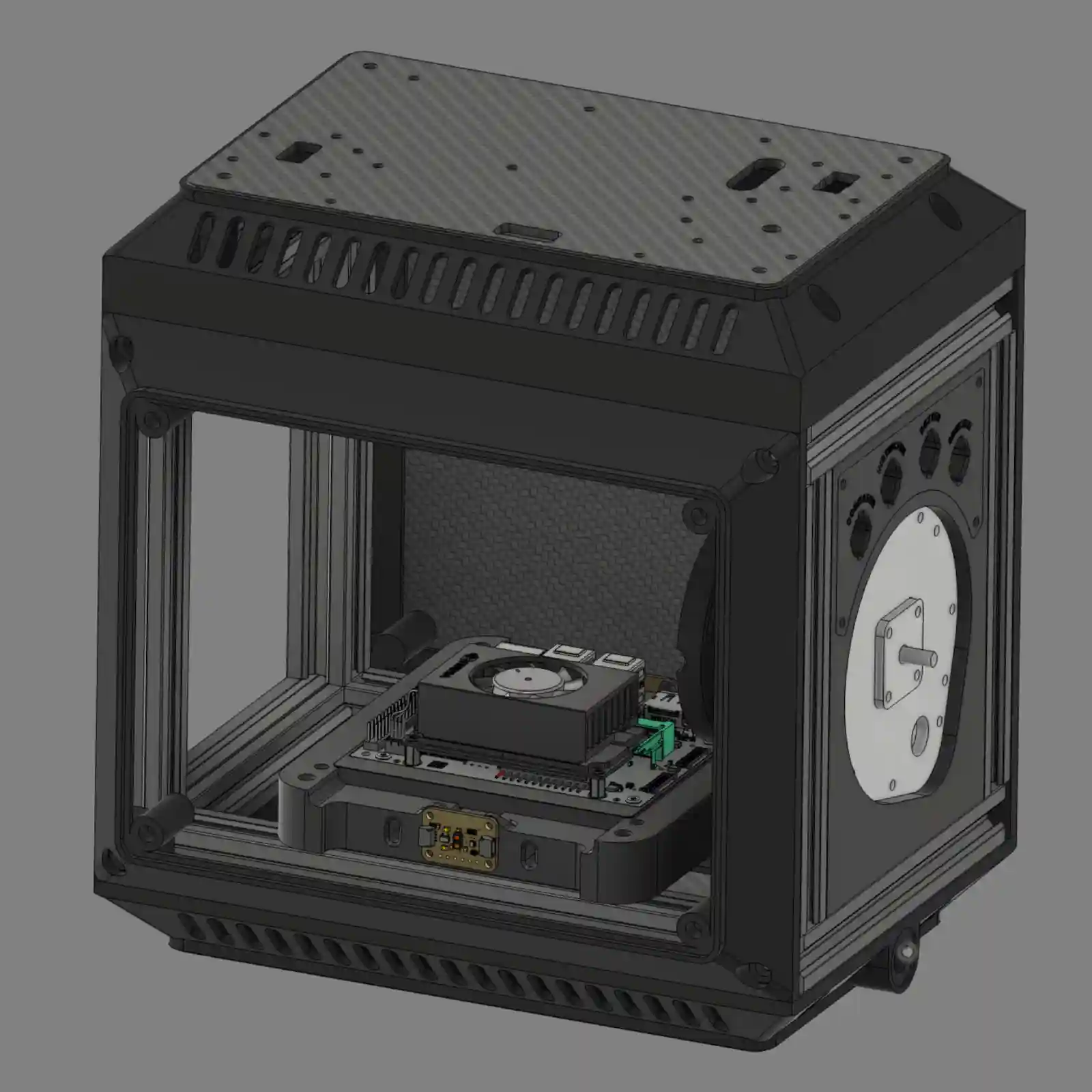
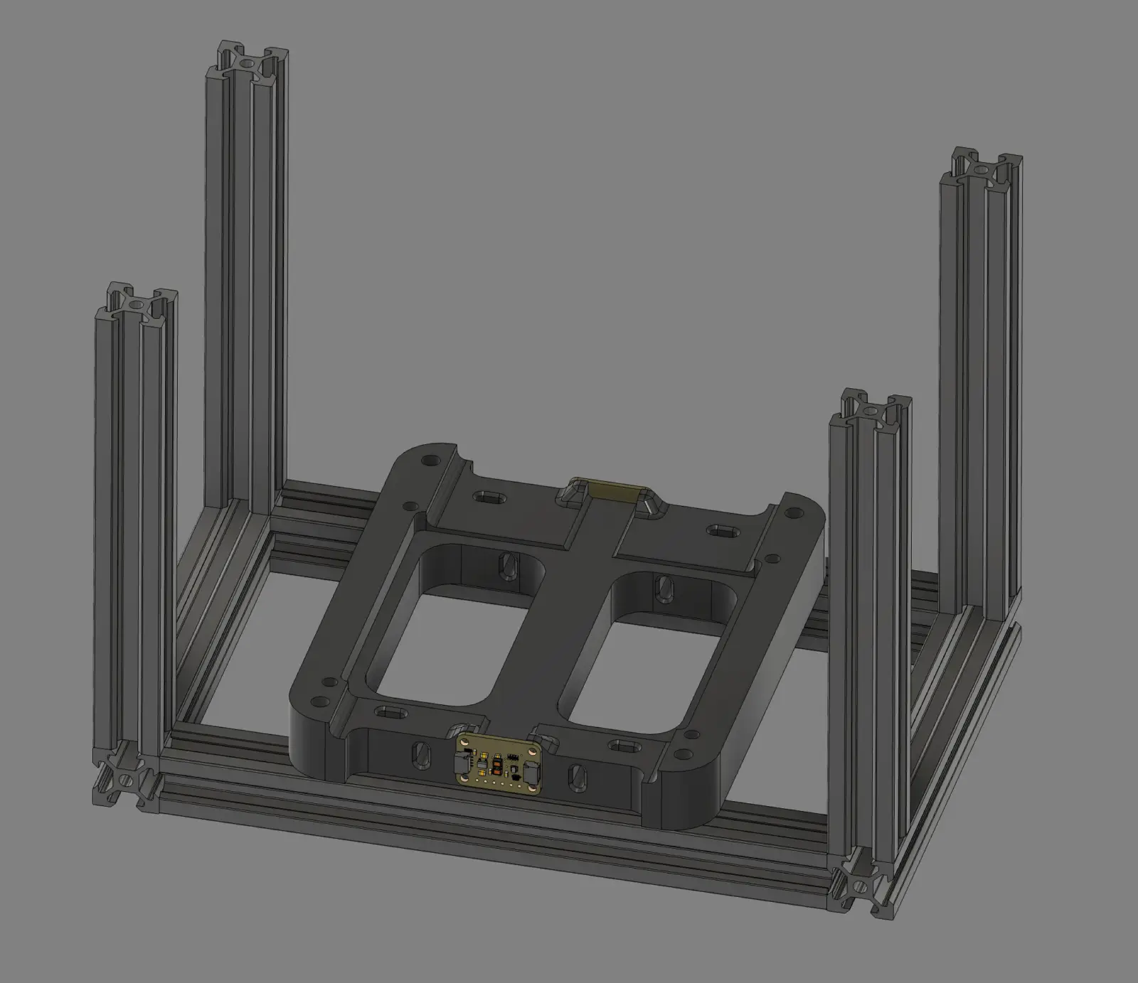
CAD render of Calvin's basic chassis.
Since the last update, I’ve received my 3.4 mm carbide drill bits. They work really well in the Carvera, although you have to do some tinkering to get the collars onto them, since you can’t pass a 3.4 mm bit through a 3.175 mm hole.
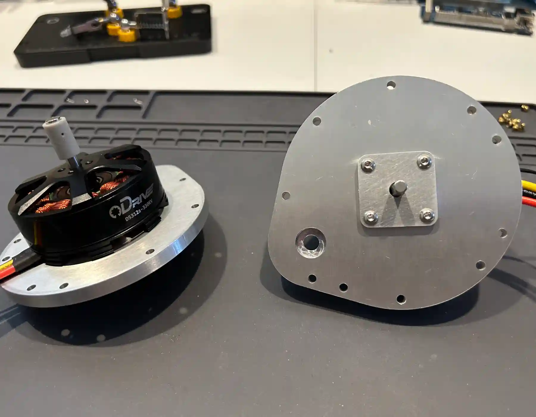
After a lot of learning and mistakes, I managed to machine the aluminum plates that hold the motors, as well as some small aluminum bearing retainers to keep the flanged bearings from falling out. The retainers could have been printed, but half the point of this project is intentionally overdoing things as a learning experience.
I’ve partially assembled the ODrive motors onto the plates. The fit is nice and tight, and they spin freely. If you look closely, you’ll see the gray magnet coupling attached to the back end of the shaft. That’s a resin print that holds and aligns the magnet needed for the ODrive encoder to work. It requires a precise fit, so I printed it with my resin printer. I could also have machined it out of brass or aluminum (something non-ferrous), but printing it was easier. I probably could have gotten away with just gluing the magnet to the end of the shaft, but I didn’t want to risk it in when doing it right is so easy.
Partially assembled motor plates with ODrive motors mounted.
The current goal is to completely assemble the chassis. Both motor plate assemblies and the printed frame pieces (top, bottom, front, and rear) are needed. The idea is to use printed frames with removable carbon fiber access panels to cover up Calvin’s internals. The frames need to fit the panels relatively precisely, so warping is a problem. And unfortunately, I had a lot of warping problems.
After a few tries with the usual tricks, I decided to try something new and ordered some PET-CF17 carbon fiber filament. I’ve never used it before, but it’s supposed to help. However, to use it, I needed a new hardened nozzle for my Prusa Core ONE printer. I’m still waiting on that, and since the motor plates are finished, I’m working on a few things I hadn’t planned to do until later.
One thing that’s already done—but will be in another post—is the label plates for the power switches on either side of the robot. I’m also working out how to machine the power and ground busses from C110 copper bar. I know I don’t need to make them so robust or precise, but it’s a good opportunity to try out the Carvera with a new material.
]]>Damon CaliPrinting Jigs2026-03-14T13:14:00+00:002026-03-14T13:14:00+00:00https://robotics.ninthyard.com/notes/2026/03/14/printing-jigsWhile I was waiting for drill bits, I decided to solve a problem that’s been bothering me for a while. The frame (made of 2020 aluminum extrusions) is slightly out of square. It wobbles when I place it on a flat surface, such as a granite countertop. This has been nagging at me because, in my experience, the extrusions are cut very precisely. Mechanical precision is important when you’re trying to get a robot not just to balance, but to balance well.
After a lot of thinking and tweaking, I came to the conclusion that I am the problem. To hold the extrusions together, I tapped the end holes with an M5 tap. That’s a good idea, except I did it too hastily—the threads were not quite straight. When you add up all the minor misalignments, you end up with a wobbly frame.
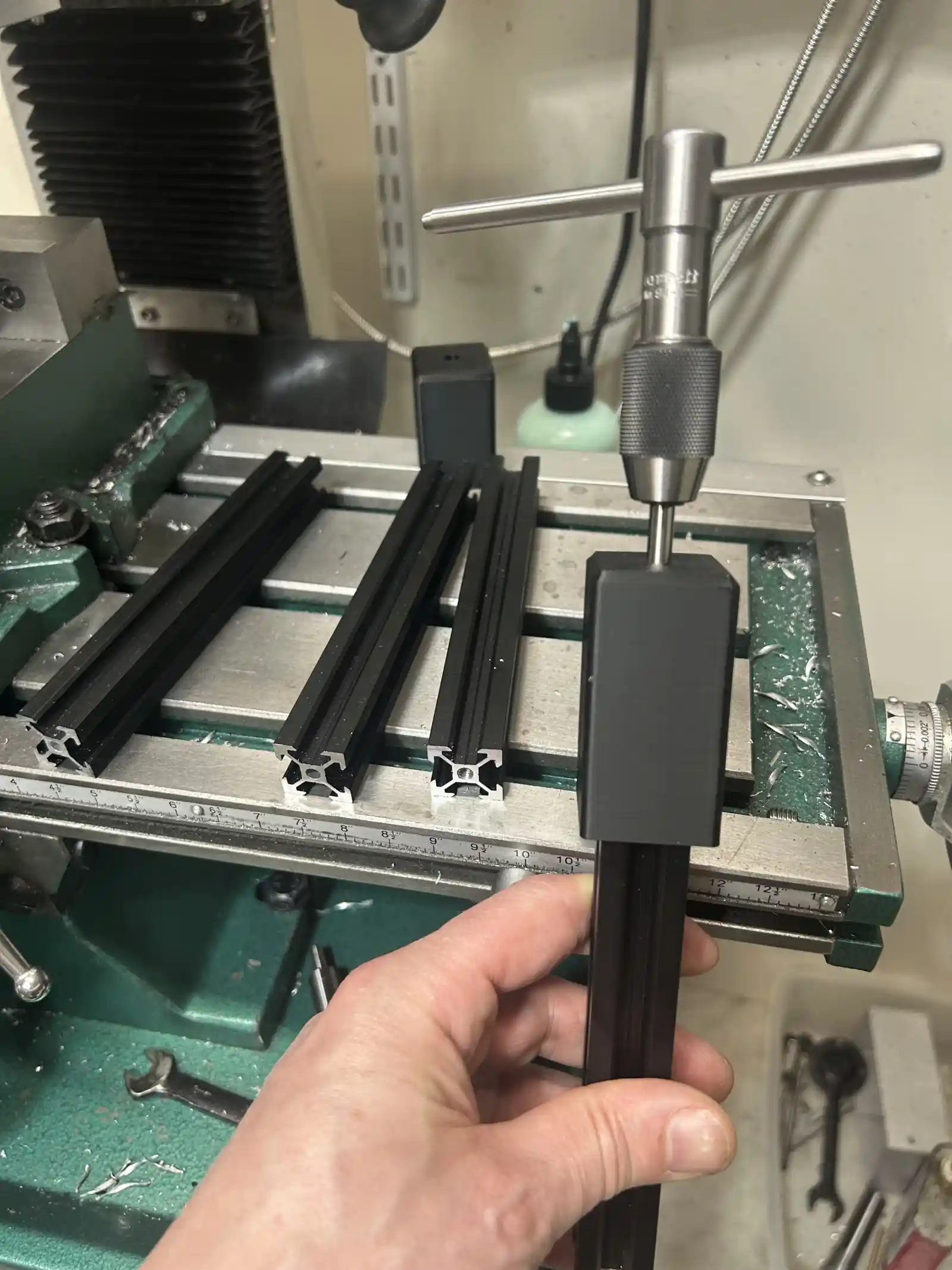
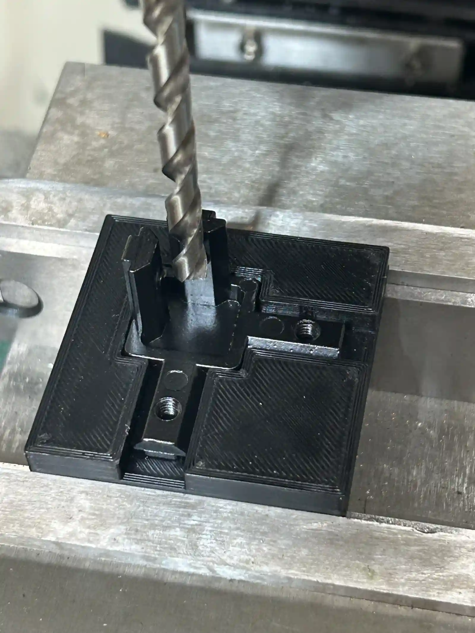
To fix this, I started over using some cast corner brackets I found on Amazon. I also decided to tap some holes in new extrusions for non-structural parts to be added later. This time, I printed jigs to keep the threads straight. I also printed another jig to drill access holes in the corner brackets.
A printed tapping jig keeps the M5 threads straight.
A second jig for drilling clearance holes in the corner brackets.
]]>Damon CaliCutting Metal2026-03-10T17:24:00+00:002026-03-10T17:24:00+00:00https://robotics.ninthyard.com/notes/2026/03/10/cutting-metalThe Teensy 4.1 has arrived. I didn’t realize it had a USB micro connector, so now I’m waiting for a USB cable. In the meantime, I decided to finally put to use the Carvera CNC mill I bought almost a year ago. Calvin’s mechanical design uses 3D-printed PLA and ABS as much as possible, but there are a few parts that really ought to be aluminum — mainly the plates that mount the motors.
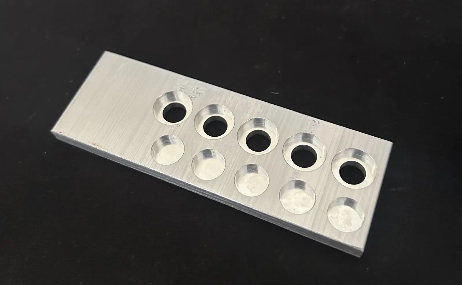
The motor plates have pockets for some 10 mm OD bearings that need to hit a pretty tight tolerance: ±0.001” on the diameter. I was a little concerned that such a small machine might not be able to hit that, but I’m happy to note that the Carvera is more than capable of that kind of precision. It does require careful setup, light passes, and a little bit of compensation in the NC code. The pockets were about 0.002” undersize, so adding negative 0.002” “stock to leave” brought them right to where they’re supposed to be. Once I sorted that out with a test part, I’m very happy with the results - the bearings are a tight slip fit. The next step is to machine the actual parts. I’m waiting on some drill bits for that, but they should be here soon.
Test piece used to dial in the Carvera.
]]>Damon CaliWireless Telemetry2026-03-05T13:51:00+00:002026-03-05T13:51:00+00:00https://robotics.ninthyard.com/notes/2026/03/05/wireless-telemetryIn the last post, I got the communication between Cogitator and Explorator working, but with a couple of constraints:
The telemetry data was not being generated by Instinctus—it was just dummy data created inside Cogitator.
Both Cogitator and Explorator were running on my Mac.
Since then, I made a small step forward by installing Cogitator on the Jetson Orin Nano and running it inside the NVIDIA Docker container that provides access to the NVIDIA software stack and device hardware. I was able to connect to the Jetson from my Mac over Wi-Fi and stream dummy data to Explorator. Basically, the same thing I did before, but now the communication works between the two devices.
The final step in this communications chain is to get the data out of Instinctus, send it to the Jetson via serial, and then pass it through Cogitator to Explorator. I’m still waiting for the Teensy to arrive, so in the meantime I’ll work on refining Explorator and planning the next services to implement in Cogitator.
]]>Damon CaliConnecting the Pipes2026-03-04T00:15:00+00:002026-03-04T00:15:00+00:00https://robotics.ninthyard.com/notes/2026/03/04/connecting-the-pipesIt’s going to take a week or so to get a Teensy 4.1 in, so work on Instinctus has stopped for a minute. Instead, I took some time to continue working out how data will flow from one system to the next. As a starting point, Instinctus will transmit ToF and IMU data to Cogitator over serial. Cogitator will take that data and make it available to Explorator over a WebSocket connection.
The Instinctus code will have to wait, but it will basically consist of a loop that reads the data and dumps it into a serial buffer on the Teensy. Nothing earth-shaking.
Cogitator is Python code written for the Jetson Orin Nano. It will be composed of several independent services coordinated by ZeroMQ. Initially, these services are:
serial: This is the counterpart to the Instinctus serial connection. It takes data off the buffer and makes it available to subscribing services through a broker.
gateway: The gateway manages WebSocket connections and serves up data for Explorator to consume.
dummy:dummy is just a drop-in replacement for serial that generates fake data so I can incrementally build and test the system. For now, it’s what I’m using.
There is also a broker- a dumb pipe that routes data from publishers to subscribers. Right now, that’s just dummy publishing and gateway subscribing.
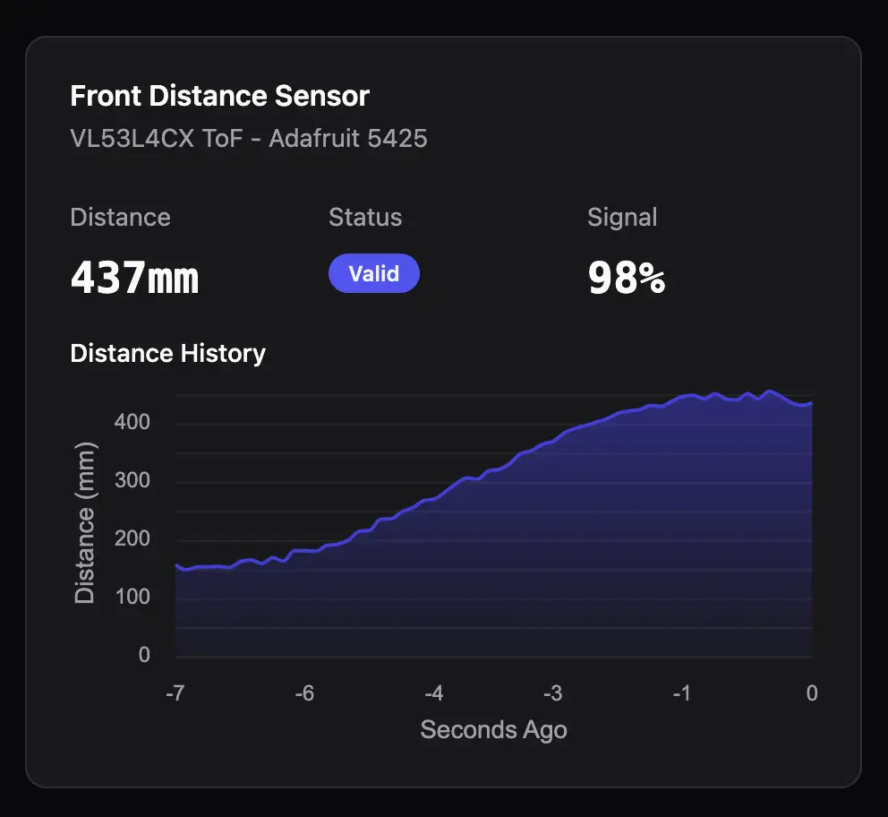
Over on Explorator, a WebSocket connection is created and maintained. For now, this is all running on my Mac, so it’s just a local connection — no Jetson involved. Data is then put in a Pania store, and UI elements react to changes. The result is a real-time chart of the data being produced by dummy. Once Instinctus is up and running, the full path from Instinctus to Cogitator to Explorator will be complete.
Real-time chart of simulated ToF data.
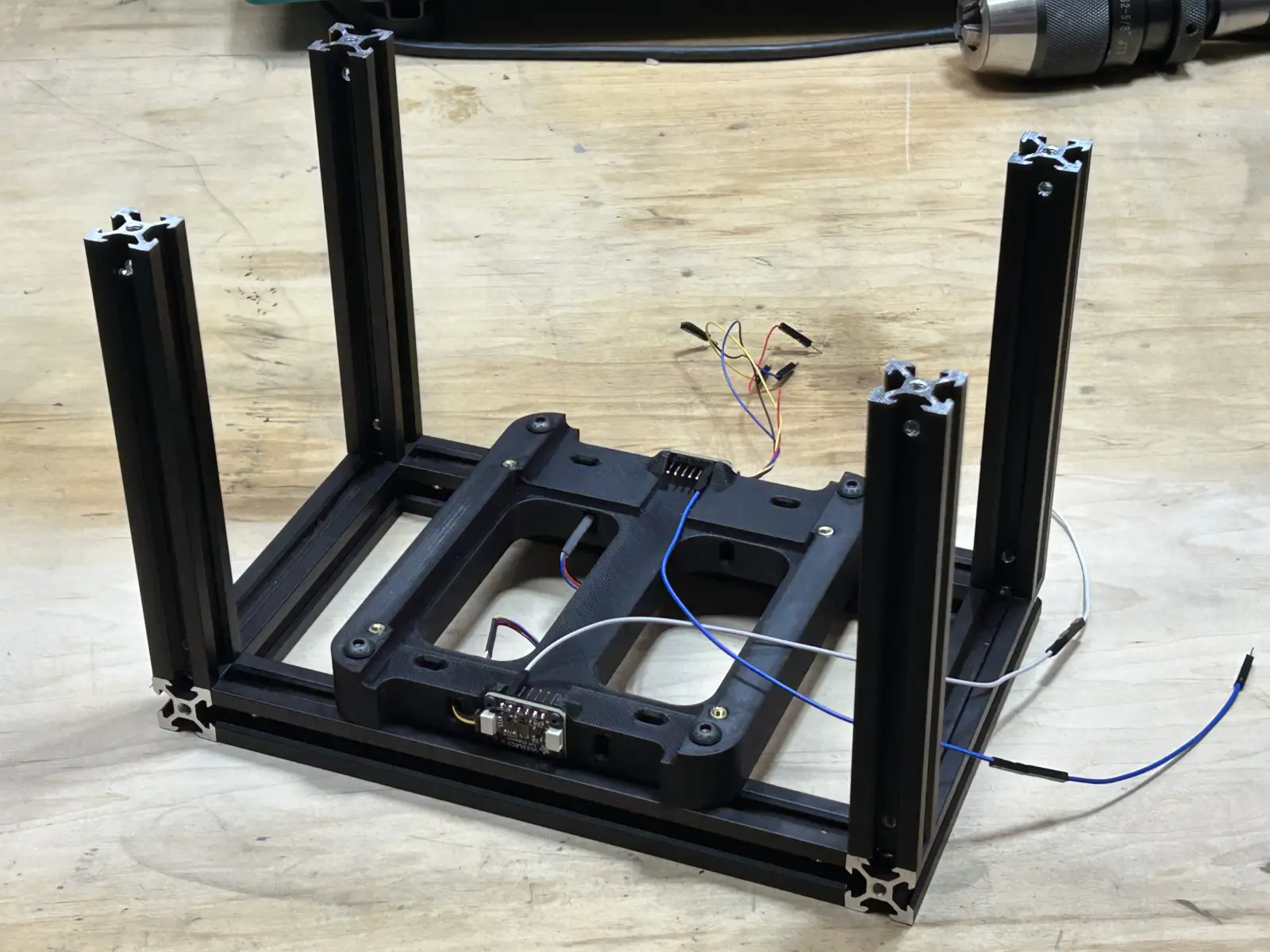
]]>Damon CaliIn the Beginning2026-03-02T16:03:00+00:002026-03-02T16:03:00+00:00https://robotics.ninthyard.com/notes/2026/03/02/in-the-beginningI had completed quite a bit of the design before creating this site, but I want to start from scratch with the build log and work through the process step by step. First up is the basic frame design and the mounting bracket for the Jetson, two ToF sensors, and the balance IMU.
The design is pretty straightforward—the frame is made from 2020 aluminum extrusions held together with M4 screws. A 3D-printed bracket holds the Jetson and sensors, keeping the IMU (mounted on the bottom of the bracket, out of sight) as close to the center of the axle as possible. Shown here are the beginnings of the frame, with the bracket and sensors in place. The Jetson will be added later.
You can see in the photograph that the three sensors are connected with I2C cables, all of which will be on the same bus. The long wires are attached to the ToF sensors’ XSHUT pins, which are used to turn the sensors on and off and to set the I2C address on boot.
Frame with sensors mounted.
Sensors daisy-chained on an I2C bus.
]]>Damon CaliRIP Arduino2026-03-02T14:30:00+00:002026-03-02T14:30:00+00:00https://robotics.ninthyard.com/notes/2026/03/02/rip-arduinoCalvin’s Arduino GIGA R1 WiFi died. Last night, I burned my finger when I briefly touched the memory chip on the board—it was extremely hot. As best I can tell, that means the board is fried, even though it’s still working (for now). How this happened is a mystery. I could have accidentally shorted something, miswired it, or it might simply be defective. In any case, it’s toast.
This gives me an opportunity to change gears in the design. I was beginning to regret going with the GIGA for a couple of reasons. First, it’s expensive (~$70) and has far more capability than I need. I primarily chose it so I could use the GIGA Display Shield, and I liked the dual-core architecture. But as I’ve gotten further into the project, the display has become less compelling. It works, but it’s slow and doesn’t provide the experience I expected. I’ve also moved on to a much more robust remote monitoring system (Calvin Explorator), which makes the display significantly less useful.
So I’m ditching the Arduino and its display and switching to a Teensy 4.1. It’s cheaper, smaller, more than capable, and has all the features I need.
One downside is that I’ll need to add Teensy support to grot, and I’m a little concerned that teensy_loader_cli won’t work on macOS 26 (Homebrew says it will, but you never know—the official docs are quite old). But one way or another, I’ll get it working.
The other downside is that the Teensy uses a single-core architecture. I liked having basic/safety functions isolated on their own core, separate from less stable systems. But without the display, the M7 core was essentially just a pass-through to the Jetson. Two cores don’t really serve a useful purpose anymore. There are also techniques to minimize the impact of non-critical code on the critical loop.
This means I have to rewrite the entire event queue system. It’s not a huge issue — just more work to be done.
]]>Damon CaliThe Event Queue2026-03-01T17:32:00+00:002026-03-01T17:32:00+00:00https://robotics.ninthyard.com/notes/2026/03/01/the-event-queueI wanted an architecture that provided maximum isolation for the M4 core. If anything were to interrupt other systems, the M4 core should remain lean and reliable. However, we still need a way for other parts of the system to send information to the M4—things like navigation targets or emergency signals generated outside the M4. The best way to do this is to create an inter-core event queue (implemented in the InstinctusKit code, which contains everything shared by both cores).
The event queue allows either core to add events and either core to process them. The only way to communicate with the M4 is through the M7 using the event queue. This is possible because a small amount of RAM is accessible to both the M7 and M4. The details are dense, but long story short, careful memory management enables safe, atomic, non-blocking communication into and out of the M4.
So what are the events? There aren’t many right now, but that will change in the future. For now, the only implemented events are:
  EVENT_BALANCE_IMU_DATA   : Sends a stream of IMU data to the M7 core (each event is a single data point).
  EVENT_TOF_DATA           : Sends a stream of data from the two ToF sensors to the M7 core.
  EVENT_PROXIMITY_WARNING  : Broadcasts a warning to both cores that an object is too close.
  EVENT_EMERGENCY_STOP     : Broadcasts a warning to both cores that power will be shut down immediately.
Events are processed by the destination core as they are received. At the moment, the M4 primarily streams data to the M7, triggers a proximity warning if the ToF sensors detect something too close, and initiates an emergency stop if the tilt angle exceeds the safe threshold.
]]>Damon CaliThe Nervous System2026-03-01T17:28:00+00:002026-03-01T17:28:00+00:00https://robotics.ninthyard.com/notes/2026/03/01/the-nervous-systemCalvin’s “nervous system” is handled by the Arduino GIGA R1 WiFi board. The GIGA is a dual-core microcontroller (M4 and M7). Both cores run separate sketches but share access to the hardware.
The most fundamental functions—balancing, motor control, and basic safety (such as object collision detection)—run on the M4 core. The only hardware attached to the M4 is an IMU and two Time-of-Flight (ToF) sensors.
The IMU is used to balance Calvin and to detect collisions by monitoring spikes in accelerometer data.
The two ToF sensors detect obstacles. One faces forward, and the other faces rearward. Their purpose is to provide a reliable indication that something is in the way without having to rely on other, less dependable systems.
The M4’s code is designed to be simple, reliable, and isolated from the more complex (and occasionally finicky) systems running on the M7 core and the Jetson. If something else fails, the M4 should still be able to provide basic functionality.